Published with permission from Fluke Corporation Introduction
In today’s process plants, most new field instruments are smart digital instruments. Smart implies a microprocessor-based instrument with extra functionality and digital compensation, supporting multiple sensor types or multiple variables. These instruments generally offer better accuracy, long-term stability, and reliability than conventional analog instruments.

The most common class of smart instruments incorporates the HART protocol, with more than five million HART instruments in use in 100,000 plants worldwide. HART, an acronym for Highway Addressable Remote Transducer, is an industry standard that defines the communications protocol between smart field devices and a control system that employs traditional 4-20 mA wiring.
Two capabilities are required to properly service HART instruments: precision analog source and measure capability and digital communication capability. Until recently, this required two separate tools, a calibrator and a communicator. Today, the capabilities of those two tools are available in a single HART Documenting Process Calibrator that can help you quickly and effectively service HART instruments.
HART calibration is required!
A common misconception is that the accuracy and stability of HART instruments eliminate the need for calibration. Another misconception is that calibration can be accomplished by re-ranging field instruments using only a HART communicator. Still another misconception is that the control system can remotely calibrate smart instruments. These are not true. All instruments drift.
Re-ranging with just a communicator is not calibration. A precision calibrator or standard is required. Regular performance verification with a calibrator traceable to national standards is necessary due to:
- Shifts in performance of electronic instruments over time, due to exposure of the electronics and the primary sensing element to temperature, humidity, pollutants, vibration, and other field environmental factors.
- Regulations governing occupational safety, consumer safety, and environmental protection.
- Quality programs such as ISO 9000 standards for all instruments that impact product quality.
- Commercial requirements such as weights, measures, and custody transfer.
Regular calibration is also prudent since performance checks will often uncover problems not directly caused by the instrumentation, such as solidified or congealed pressure lines, installation of an incorrect thermocouple type, or other errors and faults.
A calibration procedure consists of a verification (As Found) test, adjustment to within acceptable tolerance if necessary, and a final verification (As Left) test if an adjustment has been made. Data from the calibration are collected and used to complete a report of calibration, documenting instrument performance over time.
All instruments, even HART instruments, must be calibrated on a regular, preventive maintenance schedule. The calibration interval should be set short enough to insure that an instrument never drifts out of tolerance, yet long enough to avoid unnecessary calibrations. Alternatively, the interval may be determined by critical process requirements, e.g., calibration before each batch.
How are HART instruments properly calibrated?
To calibrate a HART instrument consistent with its application, it is very helpful to understand the functional structure of a typical HART transmitter. The article in Appendix A, by Kenneth L. Holladay of Southwest Research Institute, describes a typical HART instrument and defines both proper and improper calibration practices. Originally published in Intech, May 1996, it is reprinted with permission of the author.
Note: If you are unfamiliar with HART calibration or need a review, this is an excellent point to stop and read the article in Appendix A. It covers the basics of HART instrumentation and addresses issues critical to instrument maintenance.
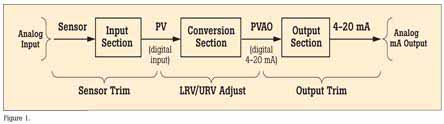
HART instruments consist of three distinct sections (see Figure 1). Proper HART calibration may involve either or both sensor trim and output trim. Adjusting range values (LRV and URV) without a calibrator is not calibration. Performing an output trim while ignoring the input section is not proper calibration. Adjusting range values with a calibrator may be a practical calibration alternative for instruments operated in 4-20 mA analog mode, provided that the PV and PVAO are not used for process control.
New tool speeds calibration
Today, instrument maintenance is moving out of the shop and into the field. This reduces process interruptions and avoids the time and expense of returning instruments to the shop. Portable communicators and calibrators are often used together to complete field calibrations. However, the desire to carry less equipment and to perform maintenance in the field has created a need for a new class of calibration tool.
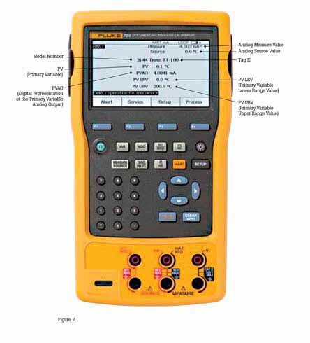
The new 754 Documenting Process Calibrator from Fluke is the first powerful yet easy-to-use tool for field calibration of HART instrumentation. Pressing a single key enters the HART mode and displays the essential HART information in the Active Device Screen, shown in Figure 2. Additional HART functionality is accessed with only a few more keystrokes, per the menu tree in Figure 3.

No communicator is required!
The 754 requires no external box or communicator for everyday HART calibration and maintenance. It supports many popular models of HART transmitters, with more device-specific command support than any other HART field calibrator.
- Interrogate HART devices to determine type, manufacturer, model, tag-ID, PV, and PVAO
- Perform automated HART sensor trim and output trim for selected devices
- Adjust ranging, damping, and other basic process—configuration settings
- Read and write HART tag and message fields to re-label smart transmitters
- Clone additional transmitters with basic HART configuration data
Versatile HART protocol support
With 64 MB of memory, the 754 supports a substantial set of HART instructions:
• Universal commands— provide functions that are implemented in all field devices, for example, read manufacturer and device type, read primary variable (PV), or read current output and percent of span
• Common practice commands— provide functions that are common to many but not all field devices, for example read multiple variables, set damping time, or perform loop test
• Device-specific commands— provide functions that are unique to a particular field device, for example sensor trim. The 754 Version supports these devices:
HART operating modes supported
• For Point to Point operation, the most commonly used mode, connects the 754 to a single HART device in a 4-20 mA loop.
• In Multi-Drop mode, several HART instruments can be bussed together. The 754 searches for each, identifies addresses in use, and allows you to select the instrument for calibration and related operations.
• In Burst Mode, the HART instrument transmits bursts of data without waiting to be interrogated by a master unit. The 754 can take transmitters out of burst mode during test or calibration, then later restore them to burst mode.
Is there still a role for the communicator?
Commissioning a HART instrument or modifying HART variables not supported by the 754 requires the use of a communicator. The 754 is designed to perform the vast majority of day-to-day operations you normally perform with a separate communicator. The HART capability of the 754 is comparable to that of the model 475 HART communicator, with the exception of the DD interpreter. While the DD interpreter enables a common communicator to read command set libraries from any HART supplier, it offers capabilities far beyond those generally required for daily HART instrument maintenance.
HART calibration applications
The following examples demonstrate how the 754 makes HART calibration an efficient operation. The 754 enables easy hookup using its HART cable, fast access to the most important HART data, automatic branching to appropriate adjustment choices, automatic completion of test templates, and automatic fetching and sending of analog readings during trim.

EXAMPLE 1
Calibration of a Rosemount 3051 HART Pressure Transmitter
Basic connections
This example assumes that the transmitter is isolated from the process and is not electrically connected to a loop power supply. Make basic connections to the 3051 per the diagram in Figure 4. A separate 250 ohm resistor is not necessary because the 754 incorporates a resistor in series with the loop supply through its mA jacks. The 3051 in this example is configured for psi units.

Procedure
- Power on the Fluke 754 Calibrator. Press the HART key followed by the Loop Power
softkey and the 754 will display the basic HART information for the 3051. - Press the HART key again and you are prompted to select the 754 configuration. Selecting
MEAS mA, SOURCE psi will configure the calibrator to measure the analog mA output and the pressure being applied simultaneously to the transmitter input and the pressure module. (Selecting MEAS PV, SOURCE psi will configure the 754 to evaluate the digital PV output from the transmitter.) Press ENTER to select. - Vent the pressure line and press CLEAR (ZERO) to zero the pressure module. Press the As Found softkey, and then press ENTER to select Instrument for a linear transmitter calibration. (If the 3051 is configured for square root output, select √ Instrument .) Notice that the calibration template is automatically completed with the exception of Tolerance. Fill in the appropriate test tolerance and press Done.
- Press the Manual Test softkey to begin calibration. Apply the input pressures ali Accept Point softkey when the correct pressure is applied for each point. When the test is complete, the error summary table is displayed. Test errors exceeding the tolerance are highlighted. When done viewing the table, press the Done >softkey. Press Done again to accept, or ENTER to change the tag, serial number or ID fields.
- If the As Found test failed (i.e., there were highlighted errors in the error summary table), adjustment is necessary. Press the Adjust softkey. Select Sensor Trim and press ENTER. (Do not select Pressure Zero Trim It is the same as trimming the lower sensor point at zero, which is useful for pressure transmitters that do not offer Sensor Trim.)
- Select Perform user trim–both and press ENTER. Zero the pressure module (vented to atmosphere) by pressing CLEAR (ZERO). Press the Continue softkey and you are prompted for the Lower Trim value. For best results, apply the LRV pressure and press Fetch to load the value being measured by the pressure module. Press Trim Then press Continue to move to the Upper Trim. As before, apply the URV pressure, press Fetch and press Trim If the 3051 is used with the digital PV output, skip to step 8 and perform the As Left test. If the 4-20 mA analog output is used in the process, continue on to step 7.
- Select Output Trim and press ENTER. The value of the primary variable (PVAO) is in the upper right corner of the display. This is normally a 4 mA signal. The mA value, as constantly measured by the Fluke 754, is in the center of the display. Press the Fetch softkey to load the measured mA value. Press Send to send the value to the 3051 to trim the output section for the 4 mA value. Press Continue for the 20 mA trim and repeat this step.
- After completing Output Trim, press the\Done softkey and proceed with the As Left verification test. Press the As Left softkey. Press Done and then press Manual Test. Apply the requested pressures and press Accept Point when the readings are stable. On completion an error summary table is displayed. If none of the errors are highlighted, the 3051 passes the calibration test. If errors are highlighted, the test has failed and further adjustment is required. Return to step 5 for adjustment of the 3051.
EXAMPLE 2
Calibration of a Rosemount 3144 HART Temperature Transmitter
Basic connections
This example assumes that the transmitter is isolated from the process and is not electrically connected to a loop power supply. Make basic connections to the 3144 per the diagram in Figure 10. A separate 250 ohm resistor is not necessary because the 754 incorporates a resistor in series with the loop supply through its mA jacks. The 3144 in this example is configured for a type K thermocouple sensor with a span of 0ºC to 300ºC.

Procedure
- Power on the Fluke 754 Calibrator. Press the HART key followed by the Loop Power softkey. Press ENTER to bypass the warning screens and the 754 will display the basic HART information for the 3144.
- Press the HART key again and you are prompted to select the 754 configuration. Selecting MEAS mA, SOURCE T/C typ K configures the calibrator to measure the analog mA output of the transmitter and source the correct temperature stimulus at the 3144 input. (Selecting MEAS PV, SOURCE T/C typ K will configure the 754 to evaluate the digital PV output from the transmitter.) Press ENTER to select.
- Press the As Found softkey, and then press ENTER to select Instrument for a linear transmitter calibration. Notice that the calibration template is automatically completed with the exception of the Tolerance. Fill in the appropriate test tolerance and press the Done softkey.
- Press the Auto Test soft-key to begin calibration. Once the test is complete, an error summary table is displayed. Test errors exceeding the tolerance are highlighted. When done viewing the table, press the Done softkey. Press Done again to accept, or ENTER to change the tag, serial number or ID fields.
- If the As Found test failed (i.e., there were highlighted errors in the error summary table), adjustment is necessary. Press the Adjust softkey. Select Sensor Trim and press ENTER. Select Perform user trim–both and press ENTER.
- For best results, press LRV to apply the LRV for the Lower Trim value. Press Trim and then Continue to move to the Upper Trim. Pres URV press Trim, and then press Done. If the 3144 is used with the digital PV output, skip to step 8 and perform the As Left test. If the analog 4-20 mA output is used in the process, continue on to step 7.
- Select Output Trim and press ENTER. The value of the primary variable (PVAO) is in the upper right corner of the display. This is normally a 4 mA signal. The mA value, as constantly measured by the Fluke 754, is in the center of the display. Press the Fetch softkey to load the measured mA value. Press Send to send the value to the 3144 to trim the output section for the 4 mA value. Press Continue for the 20 mA trim and repeat this step.
- After completing Output Trim, press the Done softkey and proceed with the As Left verification test. Press the As Left softkey. Press Done and then press Auto Test On completion, an error summary table is displayed. If errors are highlighted, the test has failed and further adjustment is required. Return to step 5 for adjustment of the 3144.
EXAMPLE 3
Calibration of HART instruments using universal commands
The 754 supports a majority of the installed workload of HART transmitters— see Table 1—by supporting sensor trim, which employs device-specific commands that are unique to a particular instrument. So how can you calibrate instruments that are not supported by the 754?
The short answer is that the 754 supports a substantial set of the universal HART commands and the common practice HART commands. The 754 can communicate with virtually any HART instrument and, in most cases, can complete a calibration procedure (except for sensor trim for unsupported instruments).
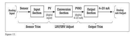
This example applies to instruments used in analog mode (4-20 mA). If the instrument is operated in digital mode, i.e., its PV is the output variable that is used for control, a calibration of the Input Section is all that is needed. Adjustment will require a Sensor Trim, (see Figure 17) which means that for instruments not supported by the 754 you will need to use both a 754 (to perform the As Found and As Left tests and record the results) and a communicator (to perform sensor trim).
For instruments used in analog mode, i.e., where the 4-20 mA analog output is used for control, the 754 can be used for calibration. After performing an As Found and determining that adjustment is required, this example first performs an Output Trim to bring the instrument within tolerance. Failing that, the example performs an adjustment to the Lower and Upper Range Values (LRV and URV) to compensate for input section error.
Note: Appendix A explains that these adjustments do not constitute a proper HART calibration. While this is true, these adjustments are a practical calibration alternative for instruments operated in 4-20 mA analog mode if error corrections are not large
How to determine digital or analog?
The transmitter is in digital mode if its HART Poll Address is set between 1 to 15. An address of 0 (zero) sets it to 4-20 mA analog output mode. The 754 will automatically connect to a device at address 0; if a device is not found at 0 the 754 will begin polling addresses 1 to 15. The 754 also displays a non-zero address with the basic HART information.
Basic connections
This example assumes that the transmitter is isolated from the process and is not electrically connected to a loop power supply. Make basic connections to the transmitter per the diagram in Figure 18. A separate 250 ohm resistor is not necessary because the 754 incorporates a resistor in series with the 24 V loop supply through its mA jacks. This example assumes a type K thermocouple transmitter with an input range of 0ºC to 100ºC, 4-20 mA output, and a 0.25% test tolerance.

Procedure
- Power on the Fluke 754 Calibrator. Press the HART key and the Loop Power softkey (if loop power is not already supplied). Press ENTER until any device warnings are cleared and the basic HART information is displayed.
- Press the HART key again and you are prompted to select the 754 configuration. Move the cursor to MEAS mA, SOURCE T/C typ K (or measure mA if source configuration is not offered), and press ENTER. (If you were verifying the digital PV instead of the mA output, i.e., the transmitter has a non-zero HART poll address, you would select MEAS PV, SOURCE T/C typ K (or measure PV if source configuration is not offered) instead.)
- If source was not configured in the previous step press the Measure/Source button and configure the source for a type K thermocouple. Press Measure/Source until you are at the dual screen. Press the As Found softkey and press ENTER to select Instrument calibration. Move the cursor to Tolerance and ENTER the appropriate test tolerance (0.25% in this example). Verify that the 0% Source Value and 100%: Source Value are the proper, nominal operating values for the transmitter (0.0ºC and 100.0ºC in this example). If the Lower (0%) and Upper (100%) Range Values (LRV and URV) have been previously modified for calibration purposes, you will need to ENTER the nominal values. For example, if a previous calibration modified the URV to 100.2ºC, you need to manually ENTER the nominal value of 100.0ºC for the 100% Value Entering nominal zero and span values ensures that errors are calculated correctly.
- Press Done and then press Auto Test. Once the test is complete, an error summary table is displayed. Test errors exceeding the tolerance are highlighted. If the test passed, i.e., if no errors are highlighted, adjustment is not required. If errors are highlighted, adjustment is necessary by performing an Output Trim. Press Done to leave the results screen, edit the tag, serial number or ID fields as necessary, and press Done again.
- Press the Adjust softkey, select Output Trim and press ENTER. The value of the primary variable (PVAO) is in the upper right corner of the display. This is normally a 4 mA signal. The real-time mA value as measured by the Fluke 754, is in the center of the display. Press the Fetch softkey to load the measured mA value. Press the Send softkey to send the value to the transmitter to trim the output section for the 4 mA value. Press Continue for the 20 mA adjustment and repeat this step.
- Now perform an As Left test. Press As Left, press Done, and then press Auto Test. On completion the error summary table is displayed. If errors are highlighted, the test has failed and further adjustment is required.
Note: If the failure error is large, sensor trim adjustment with a communicator may be necessary. Often, however, adjustment can be accomplished with a 754 by modifying the LRV (Lower Range Value) and URV (Upper Range Value) to compensate for Input Section error.
- In the case of a pressure transmitter that has onboard Zero and Span adjustment buttons, calibration is easy. Simply apply a calibrated source at the LRV and URV values and press the respective Zero and Span buttons on the transmitter. Then verify the condition of the transmitter by completing an As Left test as in step 6. Many HART transmitters do not have physical adjustments and need either a communicator or a Fluke 754 to adjust the LRV and URV values. For those cases, proceed to step 8.
- The error summary table (displayed from step 6) provides the data necessary to make LRV and URV changes. Write down the LRV and URV values (in this example 0 and 100°C). Return the 754 to the normal Measure/Source screen displaying the As Left softkey by pressing the Done softkey 3 times.
- Press the MEASURE/SOURCE button (2) times and input the LRV value (0°C this example) using the 754 keypad and press ENTER.
- Press HART and then press the Setup softkey. Select Basic from the menu and press ENTER to display the basic setup parameters. Move the cursor to Lower Range Value and press ENTER. Move the cursor to Apply Values and press ENTER. Press ENTER to select 4 mA. Press the Continue softkey, then press “any key” then press the S


